 Actually, no, it can only measure AC voltage. Note: I also got the same values when I tried to separate them like that Thanks for your advice. Thanks. So, you probably need to turn it more to see a difference in the output wave form. thanks for your great article. RunningStatistics was not declared in this scope. // put your setup code here, to run once: delay(5000); //wait for some time for the ethernet connection to be stable. Hello Yassine, For the intercept and slope you can make the input as 0 and you should have 0 then take a known value and calibrate the slope btw i really need zmpt101b fritzing part for my coursework and i see yours.
  Add now an AC voltage and check the shape of the signal, turn the potentiometer unitl you have a shape like I found, you can add a delay after the serial print if you want. Then it adds a 2.5V offset to adapt it to the Arduino. RunningStatistics inputStats; Serial.println(fBluePhaseVoltage); Sensor=2; for 3 inputs. hi, Im about to do the project that using ZMPT101b,, but, first of all I need to draw the sketch in fritzing apps. I found this GitHub: I tired to separate them to get be able to do other stuff but I didnt succed for the moment I will try to do it again, because the goal of this tutorial is just measuring.
 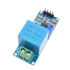 Serial.println(Serial started);
  Hello Surtrtech, float current_VoltsS; // Voltage When i was trying to remove while it says error while reading unsigned long previousMillis = 0; void setup() { Hello guys, and welcome, before we start anything, I want to warn you about messing with domestic voltage, power line, wall power. It was actually a copy paste error in my post, it is indeed ElectroPeak Inc. 2019.
  PLease help in it, Hi, I dont know what you mean by perimeters, is it something in the code or materials?? When the module is powred (with 5v) it will send 2.5V (512) to the Arduino (when theres no AC power to its input) and when you add an AC power source the voltage will be around 0-5V (0-1023) these values depend on the board ADC,for Arduino UNO its from 0-1023 10 bits). float fYellowPhaseVoltage; // stores the voltage in the Yellow Phase Im testing on a Particle.io Argon board, as this will send out messages via the Particle.io API, so I can get alerts when power is cut. I want to ask that what is the output of Module in form of DC voltages or AC if any one then what is the Mini and Max value of the Module for Arduino to formulate and display On LCD First, please make sure everything is working fine: lcd.begin(16, 2); void loop() { For the measures Im using an OLED display, you can checkMy previous tutorial, on how to use it with different examples. And heres how its derived: The graph of the sensor output voltage when it has the city electricity as its input is given as the result of the first code. but there is always 4095 or 2189 reading even I connect or disconnect cable from module ZMPT101B OR 4 Channel Bi-Directional Logic Level Shifter. Forgot to mention, using a Arduino Mega (clone) 2560, ZMPT101B, there are other things in the code but that has nothing to do with the AC voltage measuring thing, can put the full code if required. delay(1000); RunningStatistics inputStats; //Easy life lines, actual calculation of the RMS requires a load of coding float current_VoltsR; // Voltage Hi. As salam alaikm dear #include Sensor=0; you are right , I used Serial Monitor and view plotter, code run perfectly with Ardnino Un R3 , but this code does not work with ESP32. Do not use the level shifter, just the module directly with ESP32, POWERED with 3.3V/GND from the ESP and use an analog input. AC, adafruit, alternatif, Alternative, Arduino, dimmer, easy, Lcd, light, measure, measuring, module, multimeter, OLED, phase, RMS, science, screen, signal, sine, sinewave, single, square, technology, tension, triac, triangular, TRMS, tutorial, voltage, wave, zmpt101b.
  */, #include //Easy library to do the calculations, float testFrequency = 50; // test signal frequency (Hz) As you can see in the article, this module is designed to measure high voltages up to 250V. For the last line to calibrate you can remove it, if you do this. Serial.print( current_VoltsS ); //Calculation and Value display is done the rest is if you're using an OLED display, Serial.print( "\tVoltage (T): " ); Nassau, Bahamas is having terrible power issues this summer, where BPL shuts off parts of the city for 3-4 hours, rotating limited power to homes. It needs to be installed, search on how to do it. but with esp32 it does not reflect AC values in workable reading. Hi, I want to check all 3 line with 3 ZMPT101Bs. This module measures the peak-to-peak voltage. In order to calculate the input AC Voltage, you need to find the maximum of the output -Vmax_v- and use the formula given in the second code -step 3 section-. float slope = 0.0405; // to be adjusted based on calibration testing The application is simply to monitor 1-phase 120v or 2-phase 240 volts coming into house. Connect the module to the Arduino according to the following image. Please give a example to do the eletronic conection and programming to show the voltage in the displays . void setup() { Serial.print(fRedPhaseVoltage); So adapted Gerhards version in the following way. SensorS = analogRead(A1); // read the analog in value: First, Thx for this very informative post! float Volts_TRMS; // estimated actual current in amps
 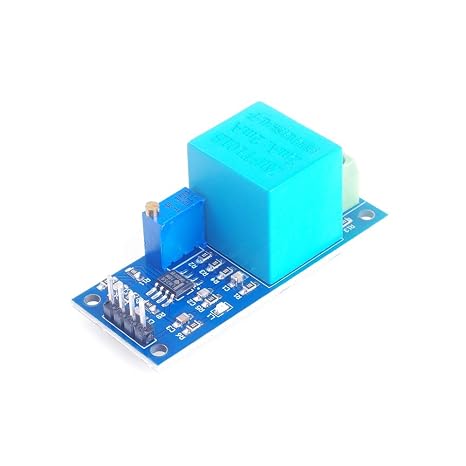 inputStats.input(RawValue); // log to Stats function, if((unsigned long)(millis() previousMillis) >= printPeriod) { it works #include //Easy library to do the calculations, used for the AC voltage thing fVoltage = fIntercept + fSlope * inputStats.sigma(); //Calibartions for offset and amplitude
  fBluePhaseVoltage = GetACVoltage(iBluePhaseSensorPin); Serial.print(Voltages R:); Hi Yassine. Suggest corrections and new documentation via GitHub. If I get this working, Ill post a .ino file back to you. if i cannt so what is the suitble code can i use? but there is always 4096 value on it. Also make sure you connect the output of the sensor to that particular pin. As you can see in the article, the image of the output of this module is provided -right above the step 3 section-. I didnt understand your explanation on that in the commwnt section as well.
  inputStats.setWindowSecs(windowLength); iSensor = analogRead(iPhasePin); //read the value from the analog pin for the RedPhase Its because reference voltage (Vref) for ADC in ESP32 is 1.1 V. So your 1.65 V translate into 4095, because its out of range. Hello, your project is very good, thanks! Any thoughts of how to do this with ZMPT ? It worked, but when i add a delay the measurement become off, do you know why? Hello, in the beginning you need the name of the library near the #include its #include First, you should use code 1 to get the maximum of the output voltage of the sensor. may i beg your zmpt101b fritzing parts? RawValue = analogRead(ZMPT101B); // read the analog in value:
  Thanks in advance, Hello, yes you can remove that while(true) loop, move the RunningStatistics inputStats; to global declarations, inputStats.setWindowSecs( windowLength ); can be set at setup, you can keep other calculations in the loop please check those articles to find some examples: For the latching relay you can just buy one too, for the 60s delay use an Arduino board if you want. Im very happy with your project, but I still experience some difficulties calibrating the readings. Im combining the ACS712 and the ZMPT101B in one code at the same time. You need 2 other variables for all: I also have a very similar application, where I have to monitor AC voltages of 3 phases. So for (3.3V/Gnd) no AC -> 1.65 its good it means theres the offset and the module is working. Im try to implement 3 phase voltage meter using esp32.. I have adjusted the Trim Pot as you suggested ..and the readings look good . current_VoltsR = current_VoltsR*(40.3231); //Further calibrations for the amplitude When you have something like this you can add a delay to see a nice sinewave, here its because Im measuring right after my light dimmer youll see a little peak before the signal peak if you measure the socket directly you wont have this. You can see the results for measuring city electricity voltage in the figure below. inputStats.setWindowSecs( windowLength ); Do you know if it is also possible to display the Frequency as well as the voltage using Filters.h library ? Hello sorry thats not a fritzing part, its just a .PNG that I integrated to fritzing. And here pay attention, some codes around are used with this module, they only do a sampling of the signal and measure the peaks then a little multiplication,and it can show you the RMS of this signal, but those codes work only for perfect sinewave signal, if youre measuring another shape of the signal it would be false. Hi. I am looking to use ZMPT101B only to monitor if our street power is ON, and therefore do not need to show graphics of sine wave. can we measure 400AC voltage and voltage Frequency ? It would be highly appreciate, if you can give me a hand.. A non TRMS Multimeter will give you a false reading for a non Sinewave signal too, as you can see the cheap one (blue) compared to our project, its 40V difference which is not good. For measuring current, you can use the following tutorials: Its actually a formula to calculate the input voltage RMS by using the maximum value of the sensor output voltage. const int iRedPhaseSensorPin = 0; //Sensor analog input, pin A0 and passed out via proper level shifter and then input it into pin15(analogread) of ESP32. -Since it is needed for calculating the RMS- Then the rest is just a linear transformation to get an output around 220 from the sensor output voltage. //float slope = 0.043; // to be adjusted based on calibration testing, //float current_Volts; // Voltage https://www.youtube.com/redirect?event=video_description&v=nExAAbO-Lc4&redir_token=6gl2uh2TPcHiTf8scjdwowsvAud8MTU1NjU0NDU0MUAxNTU2NDU4MTQx&q=http%3A%2F%2Fsentroino.blogspot.com%2F2015%2F12%2Fmeasuring-ac-voltage-using-arduino.html%3Fm%3D1, You can add a delay like i did of 100ms or swipe through some values Also try to use a different baude rate maybe, and you should use the potentiometer of the module to set its amplification otherwise the signle will not be readable But I cant give you concrete things as I didnt use it with an ESP32, Ashraf, if its still actual project for you, Ill reply. int SensorT = 2; //Sensor analog input, here it's A0, float intercept = -0.04; // to be adjusted based on calibration testing I am not sure but it does not work as signal-out value remain same. Hello, Well I tried some few stuffs and I managed to put the calculation part on a separate function that ou can call any time, this will let you do some other side stuffs. current_VoltsS = intercept + slope * inputStatsS.sigma(); //Calibartions for offset and amplitude voltage is almost 2.6v to 3.3 v on pin15. https://electropeak.com/learn/interfacing-ina219-current-sensor-module-with-arduino/ #include //Easy library to do the calculations, used for the AC voltage thing, No problem, If you have problem with calibration, you can check my latest tutorial about current sensor ACS712 I use the same method. But for the other thing (doing other stuffs beside measuring) Ill start working on it as soon as possible and if I succeded, a little video will be up with calibration summary too. This is the whole wiring, and as mentionned Im using an 12832 OLED screen you can use it or no, the module is powred by 5v and delivers an analog signal. Great video tutorial with written explanation. And about ESP32, you need to replace 511 with 2050. The calibration of the slope and intercept can be pretty tricky, its best to start from the given values then modify them a little bit, otherwise put the AC voltage to 0, remove the slope and intercept completly, current_Volts = intercept + slope * inputStats.sigma(); > current_Volts = inputStats.sigma();. The potentiometer on this module is multi-turn. btw i need zmpt101b fritzing part and i have search but i didnt find the part. The 4096 is the higher value of the Analog to Digital Converter and for it it means 3.3V, make sure its not higher (because it will keep the same value). And we already know that the input voltage RMS is 220V. Sensor=1; Thank you. Actually, to measure 2 volts, you dont need to use any module. Therefore, I need an Arduino (Particle.io) program that can monitor BPLs grid, switching OFF my homes power internally, when power is lost (will use UPS to power Arduino), then watching (with ZMPT) until BLPs power comes back on to then switch the entire house back ON again to BPLs grid. When there is no load on output (nothing is connected to infput), the sensor has an initial voltage (Offset) of VCC/2. Hello You should use ADC channel attenuation. and you already know the voltage over. { there is no change in behaviour of ZMPT101B voltage levels. thank you for your great article. I need to add that when I exceed 15 VAC, I will trigger an output of 5 V on the arduino. Another video will be up soon that uses the same method to calculate the alternating current. On the measuring function the Running statistics entity and setWindowSecs function, they need to be in loop, then the calculation and calibration should be in a separate loop. Serial.print(iPhasePin : ); Doubts on how to use Github? The output of this sensor is analog. Because I am getting like 440V instead of 220V, thank you. Learn everything you need to know in this tutorial. float slope = 1.26; // to be adjusted based on calibration testing Sir i also want to run other perimeters what can i do Thank you in advance. ==> if this works you can power the module directly from the ESP32 and use it without a level shifter. I was looking for the ZMPT101b parts library in (.fzpz) format on internet, but havent find any result. the void loop() { You can see that the maximum voltage is somewhere around 600. All Rights Reserved, Interfacing 3D Printer 20X04 LCD Smart Controller with Arduino, Interfacing DS3231 Real Time Clock RTC Module with Arduino, https://electropeak.com/learn/interfacing-acs712-current-module-with-arduino/, https://electropeak.com/learn/interfacing-ina219-current-sensor-module-with-arduino/, https://electropeak.com/learn/interfacing-zmct103c-5a-ac-current-transformer-module-with-arduino/. I use 2 moduls ZMPT to measure AC voltage, can you help me to explain more about using this moduls in one project? Hi. Serial.print( current_VoltsR ); //Calculation and Value display is done the rest is if you're using an OLED display, Serial.print( "\tVoltage (S): " ); Thank you again for the good work, Keep it UP! inputStats.input(iSensor); //log to Stats function which can be 2.5, 6 or 11 dB. The better way as I said is to use the serial plotter !!! And we already know that the input voltage RMS is 220V. lcd.setCursor(5,1); Hi
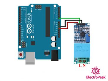
 Hello, nice tutorial I tried your code and its Woking very well. My programming is below , But the Ac Voltage measure is not right. Apologies for the double post.
  because I had the same question toda, and I responded there. Mein was based on an code I made before to measure current so I had to readjust, Hi my problem is that it deos not work ESP32, I am trying to get voltage reading on ESP32.